CWDM OADM vs MUX/DEMUX: Same Filters, Different Wiring
A 2-channel CWDM OADM module and an 8-channel CWDM MUX/DEMUX module are built from the identical filter stage, on the identical 20 nm grid. One pulls a channel off a trunk; the other combines or splits a full set of channels at an endpoint. The difference is entirely in how the stages are wired together.
Both device types on this page start from the same building block covered in our 3-Port WDM Devices note: a COM port carrying everything, a Pass port carrying what continues on, a Reflect port carrying what gets pulled off. CWDM runs this stage on a 20 nm grid, and cascades it however many times the design calls for.
Two ways to wire the same stage
Wire each stage's Pass output straight into the next stage's COM input, and add a tap or drop fiber off each Reflect port along the way, and you have an OADM (add/drop) — a device meant to sit partway through a trunk and touch only the channels it needs to. Wire every stage's Reflect output out to its own dedicated fiber instead, with nothing continuing past the last stage, and the same cascade becomes a MUX/DEMUX — a device meant to sit at an endpoint, combining every channel onto one fiber or splitting them all apart. This is the same distinction we cover for DWDM OADM, applied here to CWDM's own grid and loss numbers.
A real 2-channel OADM
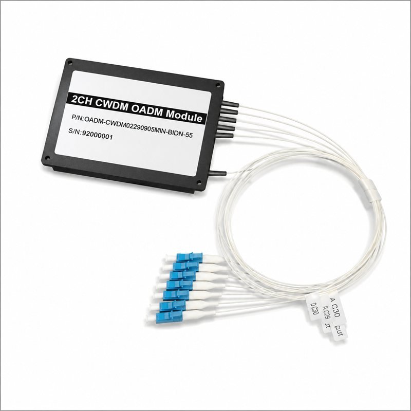
The module at the top of this page is exactly that: a 2-channel CWDM OADM, LC/UPC pigtailed, built to drop one wavelength pair off a trunk while everything else on the fiber passes through undisturbed. It is a small, purpose-built add/drop point — not a full mux/demux, and not meant to be one.
A real 8-channel MUX/DEMUX
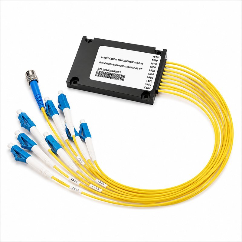
This module wires the cascade the other way: eight output legs, each carrying one CWDM channel — 1450, 1490, 1510, 1530, 1550, 1570, 1590 and 1610 nm — combined onto a single COM port with an FC connector. Note that 1470 nm is skipped: the CWDM grid runs every 20 nm from 1270 to 1610 nm, and a build populates whichever subset of those slots the application actually needs, not necessarily a contiguous run. This part is labeled for the 1260–1620 nm range and built out to 8 of the channels available in it.
The loss number that comes with more channels
Whether it’s wired as an OADM or a mux/demux, more channels means more cascaded stages, and that shows up directly in the loss budget: CWDM insertion loss runs from 0.6–1.2 dB at 2 channels up to 2.5–4.2 dB at 18 channels (the range in each case reflecting standard vs. compact packaging — covered in CWDM Packaging). An 8-channel mux/demux like the one above sits partway up that curve; a 2-channel OADM sits near the bottom of it.
Termination is a separate decision
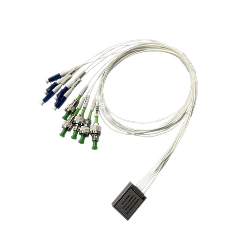
As with the rest of the WDM range, wavelength plan and termination are decided separately. This part ships with LC/UPC on some legs and FC/APC on others — whatever the customer's system needs on each connection point — without changing anything about the filter stages inside.
Specifying a CWDM OADM or MUX/DEMUX
- Add/drop vs. straight mux/demux — whether the module sits partway through a trunk or at an endpoint.
- Channel count and grid positions — which of the CWDM grid's slots from 1270 to 1610 nm the build populates.
- Package — standard or compact, per CWDM Packaging.
- Connector, per leg — set independently for each port.
Add/drop vs. mux/demux is a wiring decision made after the channel plan is set — it doesn't change what's inside the housing, only how the fibers coming off it are meant to be used.