3-Port WDM Devices: What COM, Pass and Reflect Actually Mean
Pull almost any WDM filter component out of a shipment box and count the fibers: there are three, not two. One common port carries everything in, and two branch ports each carry a defined subset out. That shape is not a single product — it is the physical form CWDM, DWDM OADM and FWDM all share, from a single wavelength pair up to a 32-channel rack module.
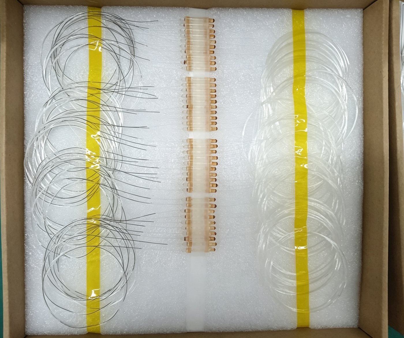
Customers who are new to the WDM catalog often ask for a “2-port wavelength combiner” and are surprised when the drawing that comes back has three fibers on it. It is not an error. A device that combines or splits wavelengths needs somewhere for each wavelength to go, and that somewhere is a physical port — which is why the simplest possible WDM filter already has three of them.
The three ports, named
Across the catalog the same three roles show up under the same names, whether the part is a single-channel filter or a 32-channel rack module:
- COM (Common) — carries every wavelength the device handles, combined onto one fiber.
- Pass — carries the wavelength (or band) that goes straight through the filter.
- Reflect — carries the wavelength (or band) that bounces off the filter instead of passing through it.
Run the device in reverse and the description flips: two signals go in on Pass and Reflect, and COM is where they come out combined. Multiplexing and demultiplexing are the same physical part read in opposite directions.
Why “reflect” is literally reflect
The naming is not arbitrary. The filter element at the core of these devices is a thin-film dichroic filter — a stack of dielectric coatings tuned so that light at one wavelength (or in one band) passes straight through it, while light at the other wavelength is reflected off its surface at an angle. Two physically different things happen to the two colors of light inside the same small package, and the port names describe exactly that: one port sees light that passed through, the other sees light that bounced off.
Same topology, every scale
A single FWDM filter is the smallest version of this shape: one wavelength pair, three ports, one small package. A DWDM OADM (add/drop) module is the same shape run at scale — a stage that pulls one ITU channel off Reflect while the entire rest of the spectrum continues through Pass, cascaded stage after stage until every channel that needs to be added or dropped has its own stage.
That cascading is exactly what shows up in the spec sheet as channel count and loss. Our DWDM platform runs insertion loss from 1.3 dB at 2 channels up to 4.8 dB at 32, because each additional channel is another COM/Pass/Reflect stage the signal has to travel through. CWDM behaves the same way on its wider 20 nm grid, from 0.6–1.2 dB at 2 channels up to 2.5–4.2 dB at 18. More channels is not a different technology — it is more three-port stages in a row.
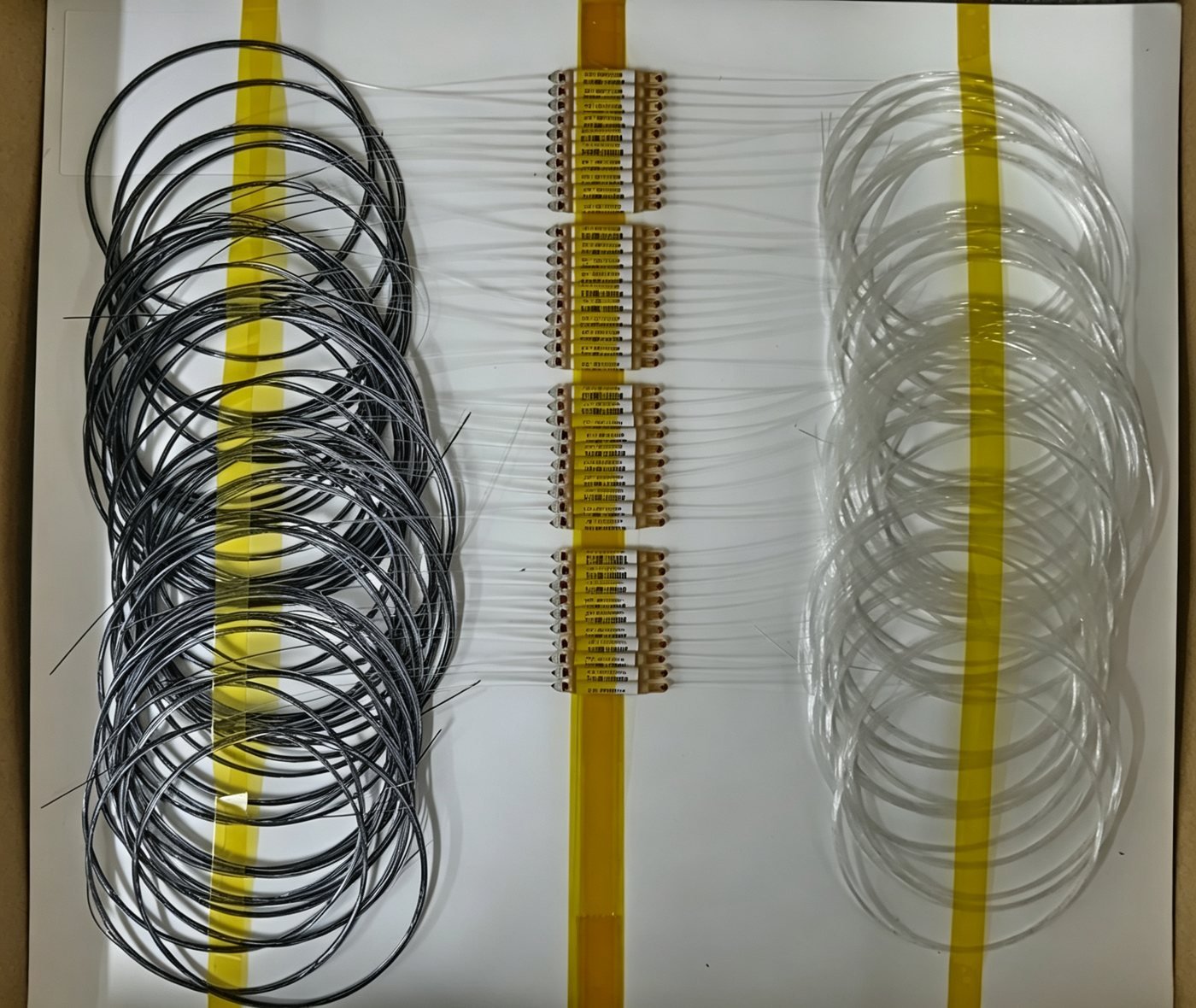
What the shipment photos actually show
The photo at the top of this page is a batch of 1×2 FWDM devices exactly as they leave assembly: three fiber legs per unit, coiled in three separate bundles, with the filter package itself sitting in the middle row. Termination is set per order — the batch above ships as bare pigtail, ready for the customer to splice or connectorize in their own process.
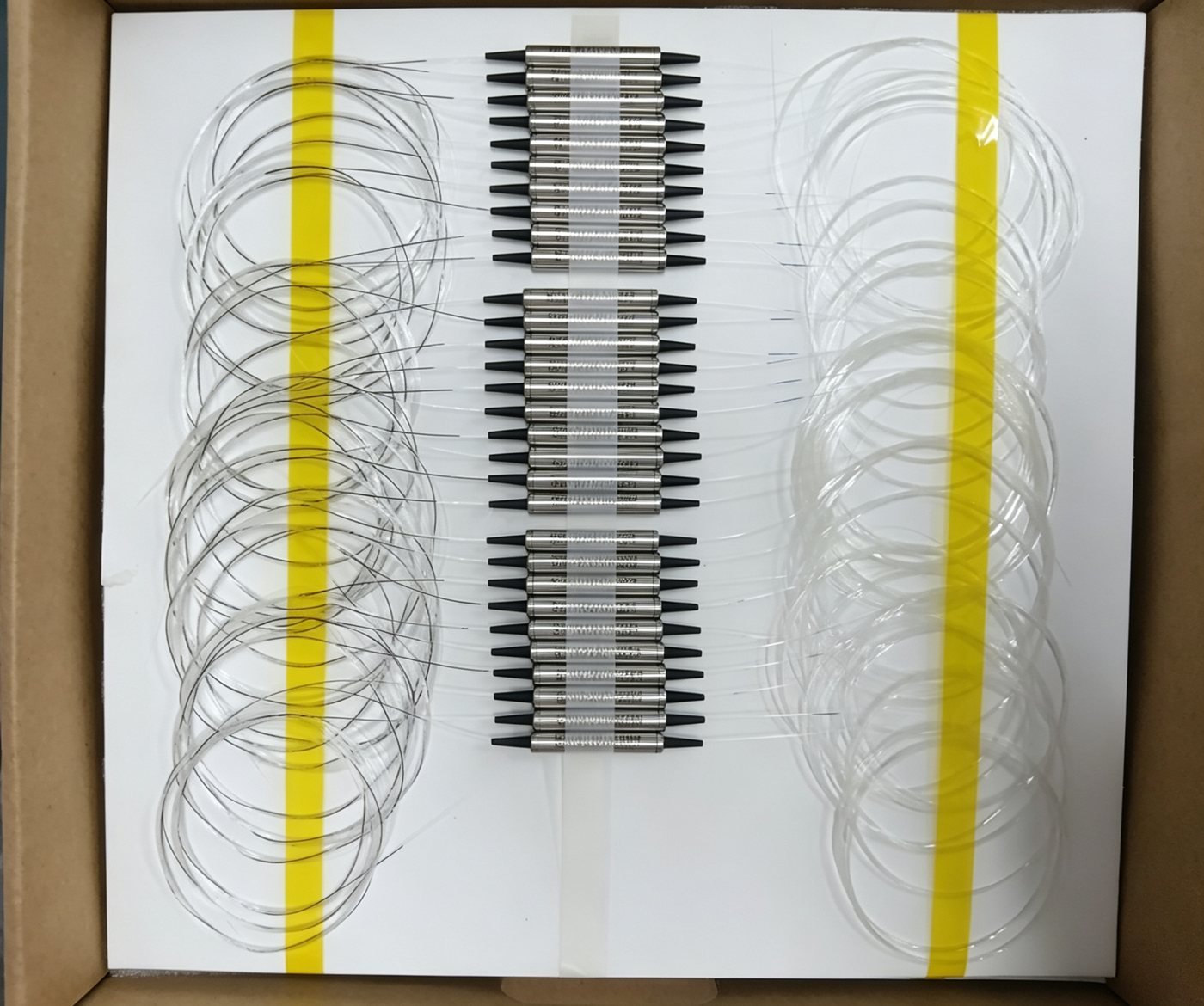
Nothing about the underlying part changes between the two photos — same filter, same three ports, same COM/Pass/Reflect assignment. The only thing that differs is where in the process the customer wants to take over: bare fiber for their own termination line, or a fully connectorized part ready to plug straight into a system.
Not every three-port device is a wavelength splitter
It is worth being precise here, because the same three-leg shape shows up on a completely different device: the optical tap coupler. A tap coupler also has one common-side port and two branch ports, but it splits light by power ratio, not by wavelength — a fixed percentage of whatever light arrives (5% up to 50%) goes to the monitor leg, and the rest continues on the through path, regardless of what wavelength it is.
Specifying one
Whichever member of the family you need, the questions that actually determine the build are the same shape across the whole WDM & TAP range:
- What goes on COM, and what splits onto Pass and Reflect — a wavelength pair for FWDM, a channel plan and grid for CWDM/DWDM, a tap ratio for a tap coupler.
- Package — standard or compact housing, and the outline that fits your stack-up.
- Fiber length and connector — bare pigtail through to any standard connector, fitted per leg.
- Whether you need a monitor port — available on most of the range as a fourth, low-power tap on top of the base three-port structure.
Get the first one right and the rest of the RFQ is mostly packaging. Get it wrong and no amount of package tuning fixes a filter built for the wrong wavelength pair.