DWDM OADM: Adding and Dropping a Single ITU Channel
An OADM stage pulls one ITU channel off a DWDM trunk — or puts one onto it — while every other channel on the fiber continues through undisturbed. It runs on the same three-port COM/Pass/Reflect platform as the rest of the WDM line, cascaded as many times as there are channels to touch.
“Add/drop” describes what happens at one point on a DWDM network: a single wavelength channel is pulled off the trunk fiber (dropped) for local termination, or a new signal is inserted onto that same wavelength (added), while every other channel already on the fiber passes straight through, unaware anything happened. An OADM (optical add/drop multiplexer) is the component that does this without disturbing the rest of the spectrum.
The add/drop stage is a COM/Pass/Reflect filter
Physically, one add/drop stage is exactly the same three-port filter described across the rest of the WDM line: COM carries the full multi-wavelength trunk, Pass carries every channel except the one being touched, and Reflect carries just the one channel being dropped — or, run in reverse, added. Our DWDM platform builds this in both configurations on the same hardware:
Why loss scales with channel count
Handling more channels on a DWDM OADM means cascading more of these three-port stages in series — each additional channel the module has to add, drop or pass through is another filter the signal travels across. That shows up directly in the insertion loss specification:
| Channel count | Port insertion loss |
|---|---|
| 2 | 1.3 dB |
| 4 / 8 / 16 | scales between the two endpoints |
| 32 | 4.8 dB |
Channel count runs 2, 4, 8, 16 or 32, with insertion loss scaling from the 1.3 dB and 4.8 dB endpoints above as more filter stages are cascaded to hold the tighter DWDM channel spacing (100 or 200 GHz, against CWDM’s much wider 20 nm grid). More channels is not a different technology tier — it is more stages in a row, and every stage costs a small, predictable amount of loss. Ask for the exact figure at your channel count when you request a datasheet.
Where on the grid, and how wide a package
Center wavelength follows the ITU grid from C11 to C64, covering the primary C-band range of 1525–1565 nm, with a monitor port available separately across 1260–1360 nm. Packaging scales from a compact 80×58×8 mm module at the low end up to a 482×250×44 mm 19″ rack unit for the highest channel counts and add/drop configurations.
What these shipment photos actually are
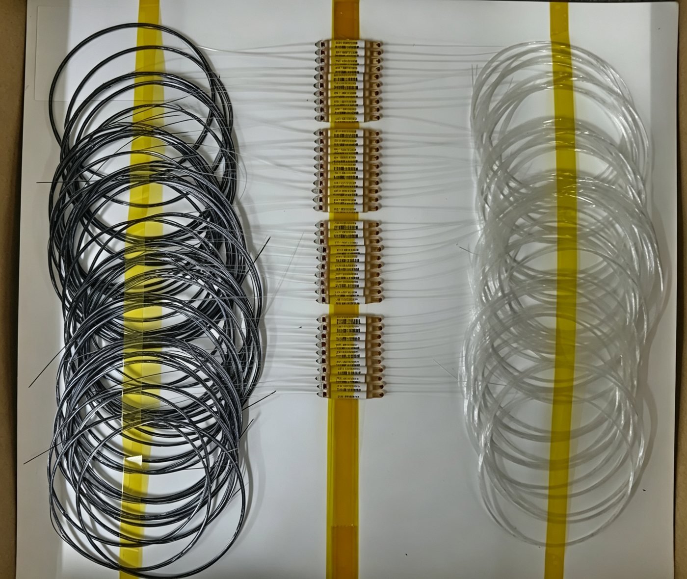
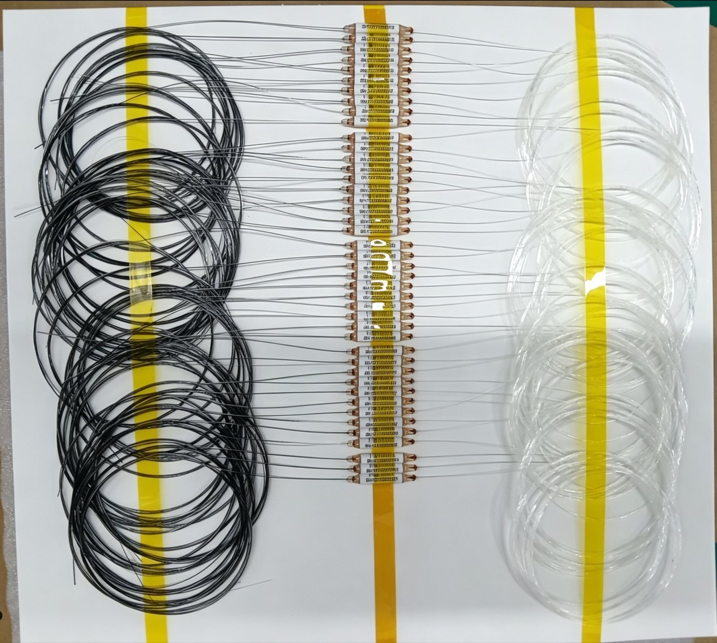
Both photos on this page are single-channel DWDM filter devices — one batch built to the C27 grid position, the other to C35. Each individual unit is one COM/Pass/Reflect stage tuned to one specific ITU channel, shipped as a discrete component with three fiber legs, exactly like the FWDM devices covered elsewhere on this blog. Customers use parts like these two ways: dropped straight into their own system as a single add/drop point, or cascaded together with other channel positions to build up a multi-channel OADM assembly. The channel-specific serial numbers on each unit’s label track back to that exact grid position — a C27 filter and a C35 filter are not interchangeable parts, even though nothing about the package tells them apart at a glance.
Specifying a DWDM OADM
The build is set by:
- Channel count — 2, 4, 8, 16 or 32, matched to how many wavelengths the add/drop site actually needs to touch.
- ITU grid position(s) — C11 through C64, one grid position per channel being added or dropped.
- Add/drop vs straight mux/demux — whether channels are being pulled off partway through the trunk or combined/split at the endpoints.
- Package and connector — from a compact module to a full 19″ rack unit, connectorized to your system.
The channel count and grid positions are the two lines that actually define the optical design; everything else is packaging built around that core.